Difference between revisions of "Block attributes"
m (→Roof triangle fans) |
Dummiesman (talk | contribs) (→Texture references) |
||
| (38 intermediate revisions by 2 users not shown) | |||
| Line 16: | Line 16: | ||
|[[#Roads with sidewalks|0x00]]||n||Road with sidewalks | |[[#Roads with sidewalks|0x00]]||n||Road with sidewalks | ||
|- | |- | ||
| − | |[[#Sidewalk | + | |[[#Sidewalk strip|0x01]]||n||Sidewalk strip |
|- | |- | ||
|[[#Roads without sidewalks|0x02]]||n||Road without sidewalks | |[[#Roads without sidewalks|0x02]]||n||Road without sidewalks | ||
| Line 22: | Line 22: | ||
|[[#Slivers|0x03]]||4||Sliver | |[[#Slivers|0x03]]||4||Sliver | ||
|- | |- | ||
| − | |0x04|| | + | |[[#Crosswalk rectangles|0x04]]||4||Crosswalk rectangle |
|- | |- | ||
| − | |0x05||n||Road triangle fan | + | |[[#Road triangle fans|0x05]]||n||Road triangle fan |
|- | |- | ||
|[[#Triangle fans|0x06]]||n||Triangle fan | |[[#Triangle fans|0x06]]||n||Triangle fan | ||
| Line 32: | Line 32: | ||
|[[#Divided roads|0x08]]||n||Divided road | |[[#Divided roads|0x08]]||n||Divided road | ||
|- | |- | ||
| − | |0x09|| | + | |[[#Road tunnel/railing|0x09]]||3||Road tunnel/railing |
|- | |- | ||
| − | |0x09|| | + | |[[#Junction tunnel/railing|0x09]]||0||Junction tunnel/railing |
|- | |- | ||
|[[#Texture references|0x0a]]||n||Texture reference | |[[#Texture references|0x0a]]||n||Texture reference | ||
|- | |- | ||
| − | |0x0b||6||Facade | + | |[[#Facades|0x0b]]||6||Facade |
|- | |- | ||
|[[#Roof triangle fans|0x0c]]||n||Roof triangle fan | |[[#Roof triangle fans|0x0c]]||n||Roof triangle fan | ||
| − | |||
| − | |||
| − | |||
| − | |||
| − | |||
| − | |||
|} | |} | ||
| Line 55: | Line 49: | ||
===Texture references=== | ===Texture references=== | ||
| − | Most geometry primitives use texture mappings. The textures are identified by attributes of type ''0xa''. The data is just one byte and a padding zero byte. The byte is an eight bit index in the list of materials. In order to be able to use more than 256 textures, the subtype indicates a value to add to the byte to get the real index. This formula can be used to compute the real index, ''n'': ''n'' = ''data'' + (256 * ''subtype'') - 1. The data value 0 in subtype 0 is special, it | + | Most geometry primitives use texture mappings. The textures are identified by attributes of type ''0xa''. The data is just one byte and a padding zero byte. The byte is an eight bit index in the list of materials. In order to be able to use more than 256 textures, the subtype indicates a value to add to the byte to get the real index. This formula can be used to compute the real index, ''n'': ''n'' = ''data'' + (256 * ''subtype'') - 1. The data value 0 in subtype 0 is special, it prevents rendering and collision on attributes that use it. |
| − | |||
Several block attributes use more than one texture. In most cases the texture attribute references the first texture in a list. This texture index is referenced to as texture ''n'' and block attributes sometimes uses texture index ''n'', ''n + 1'', ''n + 2'', ''n + 3'' and so on. | Several block attributes use more than one texture. In most cases the texture attribute references the first texture in a list. This texture index is referenced to as texture ''n'' and block attributes sometimes uses texture index ''n'', ''n + 1'', ''n + 2'', ''n + 3'' and so on. | ||
| Line 77: | Line 70: | ||
struct TriangleFan | struct TriangleFan | ||
{ | { | ||
| − | bit | + | bit lastAttribute; |
| − | bit[4] | + | bit[4] type = 0x06; |
| − | bit[3] | + | bit[3] subtype = 0x00; |
| − | bit[8] | + | bit[8] padding = 0x00; |
| − | ushort | + | ushort nTriangles; |
| − | ushort[ | + | ushort[nTriangles + 2] vertexRefs; // Indices in the vertex list |
} | } | ||
| Line 103: | Line 96: | ||
struct Walkway | struct Walkway | ||
{ | { | ||
| − | bit | + | bit lastAttribute; |
| − | bit[4] | + | bit[4] type = 0x02; |
| − | bit[3] | + | bit[3] subtype = 0x00; |
| − | bit[8] | + | bit[8] padding = 0x00; |
| − | ushort | + | ushort nSections; // Number of cross sections |
| − | ushort[ | + | ushort[nSections * 2] vertexRefs; // Indices in the vertex list |
} | } | ||
struct Walkway | struct Walkway | ||
{ | { | ||
| − | bit | + | bit lastAttribute; |
| − | bit[4] | + | bit[4] type = 0x02; |
| − | bit[3] | + | bit[3] subtype > 0x01; |
| − | bit[8] | + | bit[8] padding = 0x00; |
| − | ushort[ | + | ushort[subtype * 2] vertexRefs; // Indices in the vertex list |
} | } | ||
| Line 124: | Line 117: | ||
The most common roads in an MM2 city are the ones with sidewalks on both sides. These are easily defined using cross-sections of the road. Attribute 0x00 defines cross sections of the particular road segment. | The most common roads in an MM2 city are the ones with sidewalks on both sides. These are easily defined using cross-sections of the road. Attribute 0x00 defines cross sections of the particular road segment. | ||
| − | The vertices in each cross section are organized like this: First comes the vertex defining the position of the outer edge of the left sidewalk, then follows the outer edge of the left road surface, the outer edge of the right road surface and finally the outer edge of the right sidewalk. MM2 automatically renders the vertical sides of the sidewalks and the road surface vertices are expected to be located 15 | + | The vertices in each cross section are organized like this: First comes the vertex defining the position of the outer edge of the left sidewalk, then follows the outer edge of the left road surface, the outer edge of the right road surface and finally the outer edge of the right sidewalk. MM2 automatically renders the vertical sides of the sidewalks and the road surface vertices are expected to be located 0.15 units below the sidewalk vertices. |
This type of roads use three textures. The texture attribute points out texture ''n'', this texture is used to render the road surface. This texture is mirrored along the center line of the road. The sidewalks are rendered using texture ''n'' + 1 and texture ''n'' + 2 is the texture used across the entire road in the lowest ''LOD'', or level of detail, of the road segment. | This type of roads use three textures. The texture attribute points out texture ''n'', this texture is used to render the road surface. This texture is mirrored along the center line of the road. The sidewalks are rendered using texture ''n'' + 1 and texture ''n'' + 2 is the texture used across the entire road in the lowest ''LOD'', or level of detail, of the road segment. | ||
| Line 130: | Line 123: | ||
struct Road | struct Road | ||
{ | { | ||
| − | bit | + | bit lastAttribute; |
| − | bit[4] | + | bit[4] type = 0x00; |
| − | bit[3] | + | bit[3] subtype = 0x00; |
| − | bit[8] | + | bit[8] padding = 0x00; |
| − | ushort | + | ushort nSections; // Number of cross sections |
| − | ushort[ | + | ushort[nSections * 4] vertexRefs; // Indices in the vertex list |
} | } | ||
struct Road | struct Road | ||
{ | { | ||
| − | bit | + | bit lastAttribute; |
| − | bit[4] | + | bit[4] type = 0x00; |
| − | bit[3] | + | bit[3] subtype != 0x00; |
| − | bit[8] | + | bit[8] padding = 0x00; |
| − | ushort[ | + | ushort[subtype * 4] vertexRefs; // Indices in the vertex list |
} | } | ||
===Divided roads=== | ===Divided roads=== | ||
[[Image:0x08 Divided road.jpg|thumb|350px]] | [[Image:0x08 Divided road.jpg|thumb|350px]] | ||
| − | The vertices in each cross section are organized like this: First comes the vertex defining the position of the outer edge of the left sidewalk, then follows the outer edge of the left road surface, the inner edge of the left road surface, the inner edge of the right road surface, the outer edge of the right road surface and finally the outer edge of the right sidewalk. MM2 automatically renders the vertical sides of the sidewalks and the road surface vertices are expected to be located 15 | + | The vertices in each cross section are organized like this: First comes the vertex defining the position of the outer edge of the left sidewalk, then follows the outer edge of the left road surface, the inner edge of the left road surface, the inner edge of the right road surface, the outer edge of the right road surface and finally the outer edge of the right sidewalk. MM2 automatically renders the vertical sides of the sidewalks and the road surface vertices are expected to be located 0.15 units below the sidewalk vertices. |
The road surface and sidewalks are rendered in the same way as the road with sidewalk attributes. | The road surface and sidewalks are rendered in the same way as the road with sidewalk attributes. | ||
| Line 155: | Line 148: | ||
====Divider type==== | ====Divider type==== | ||
| − | Several types of dividers can be created by using various parameters to the divided road strip attributes. First we have a flags parameter, the flags | + | Several types of dividers can be created by using various parameters to the divided road strip attributes. First we have a flags parameter, the flags parameter is divided into two parts, it is currently not 100% clear how many bits belong to which part, but the examined road attributes in SF and London indicates that at least the two lowest bits of the flags parameter is a divider type. |
In addition to the flags parameter there is also an extra texture reference and a value parameter. These are used differently depending on the divider type. | In addition to the flags parameter there is also an extra texture reference and a value parameter. These are used differently depending on the divider type. | ||
| Line 181: | Line 174: | ||
bit[8] padding = 0x00; | bit[8] padding = 0x00; | ||
ushort nSections; | ushort nSections; | ||
| − | + | bit[5] flags; | |
| + | bit[3] dividerType; | ||
ubyte texture; // Index in the texture list + 1 for the divider | ubyte texture; // Index in the texture list + 1 for the divider | ||
| + | ushort value; // Usage depends on the divider type | ||
ushort[nSections * 6] vertexRefs; // Indices in the vertex list | ushort[nSections * 6] vertexRefs; // Indices in the vertex list | ||
} | } | ||
| Line 192: | Line 187: | ||
bit[3] subtype != 0x00; | bit[3] subtype != 0x00; | ||
bit[8] padding = 0x00; | bit[8] padding = 0x00; | ||
| − | + | bit[5] flags; | |
| + | bit[3] dividerType; | ||
ubyte texture; // Index in the texture list + 1 for the divider | ubyte texture; // Index in the texture list + 1 for the divider | ||
| + | ushort value; // Usage depends on the divider type | ||
ushort[subtype * 6] vertexRefs; // Indices in the vertex list | ushort[subtype * 6] vertexRefs; // Indices in the vertex list | ||
} | } | ||
| Line 202: | Line 199: | ||
===Sidewalk strip=== | ===Sidewalk strip=== | ||
[[Image:Roadcrossing Sidewalk.jpg|thumbnail|350px|Sidewalk strip attribute]] | [[Image:Roadcrossing Sidewalk.jpg|thumbnail|350px|Sidewalk strip attribute]] | ||
| − | A sidewalk strip defines a piece of a sidewalk. The sidewalk is defined by a set of inner and outer vertex indices, repeating a vertex index can be used to ''bend'' a sidewalk around a point as shown in the image. The actual geometry will have an additional point 15 | + | A sidewalk strip defines a piece of a sidewalk. The sidewalk is defined by a set of inner and outer vertex indices, repeating a vertex index can be used to ''bend'' a sidewalk around a point as shown in the image. The actual geometry will have an additional point 0.15 units above the inner vertex of each cross section. |
| + | |||
| + | ====Road end piece==== | ||
| + | [[Image:0x0A_Sidewalk_Strip.jpg|thumbnail|left|250px|Road end piece]] | ||
| + | A special end piece for roads can be made using sidewalk strip attribute ''0xa''. Normally this attribute makes a regular sidewalk strip with 4 vertices. However, if the first two vertex references are both set to ''0'' or ''1'', this attribute makes up a single triangle begin piece or end piece respectively. Vertex references 3 and 4 define the two bottom vertices for the end piece. Another vertex is generated 0.15 units above vertex 3 (vertex 1 in the picture) to form the triangle. | ||
| + | |||
{{Clr}} | {{Clr}} | ||
struct SidewalkStrip | struct SidewalkStrip | ||
{ | { | ||
| − | bit | + | bit lastAttribute; |
| − | bit[4] | + | bit[4] type = 0x01; |
| − | bit[3] | + | bit[3] subtype = 0x00; |
| − | bit[8] | + | bit[8] padding = 0x00; |
| − | ushort | + | ushort nSections; // Number of cross-sections |
| − | ushort[ | + | ushort[nSections * 2] vertexRefs; // Indices in the vertex list |
} | } | ||
struct SidewalkStrip | struct SidewalkStrip | ||
{ | { | ||
| − | bit | + | bit lastAttribute; |
| − | bit[4] | + | bit[4] type = 0x01; |
| − | bit[3] | + | bit[3] subtype > 0x01; |
| − | bit[8] | + | bit[8] padding = 0x00; |
| − | ushort | + | ushort[subtype * 2] vertexRefs; // Indices in the vertex list |
| − | ushort[ | + | } |
| + | |||
| + | ===Crosswalk rectangles=== | ||
| + | A rectangular surface representing a cross-walk. | ||
| + | {{Clr}} | ||
| + | struct CrosswalkRectangle | ||
| + | { | ||
| + | bit lastAttribute; | ||
| + | bit[4] type = 0x04; | ||
| + | bit[3] subtype = 0x04; | ||
| + | bit[8] padding = 0x00; | ||
| + | ushort[subtype] vertexRefs; // Indices in the vertex list | ||
| + | } | ||
| + | |||
| + | ===Road triangle fans=== | ||
| + | A road triangle fan is encoded the same way as a regular triangle fan. | ||
| + | {{Clr}} | ||
| + | struct RoadTriangleFan | ||
| + | { | ||
| + | bit lastAttribute; | ||
| + | bit[4] type = 0x05; | ||
| + | bit[3] subtype = 0x00; | ||
| + | bit[8] padding = 0x00; | ||
| + | ushort nTriangles; // Number of triangles | ||
| + | ushort[nTriangles + 2] vertexRefs; // Indices in the vertex list | ||
| + | } | ||
| + | |||
| + | struct RoadTriangleFan | ||
| + | { | ||
| + | bit lastAttribute; | ||
| + | bit[4] type = 0x05; | ||
| + | bit[3] subtype != 0x00; | ||
| + | bit[8] padding = 0x00; | ||
| + | ushort[subtype + 2] vertexRefs; // Indices in the vertex list | ||
} | } | ||
==Buildings== | ==Buildings== | ||
| − | Most of the buildings in a city is constructed using PSDL attributes. These are well suited for low detailed buildings. For higher detail levels, add INST-placed PKGs as parts of or complete buildings. | + | Most of the buildings in a city is constructed using PSDL attributes. These are well suited for low detailed buildings. For higher detail levels, add [[INST]]-placed PKGs as parts of or complete buildings. |
===Roof triangle fans=== | ===Roof triangle fans=== | ||
| − | The roof of a building is made up of triangle fans | + | The roof of a building is made up of triangle fans. These fans differ from the regular triangle fan in that the vertex count is indicated differently. Another difference is that they include a reference to a height value that will replace the y-component of each of the referenced points. |
{{Clr}} | {{Clr}} | ||
struct RoofTriangleFan | struct RoofTriangleFan | ||
| Line 236: | Line 271: | ||
bit[3] subtype = 0x00; | bit[3] subtype = 0x00; | ||
bit[8] padding = 0x00; | bit[8] padding = 0x00; | ||
| − | ushort nVertices - 1 | + | ushort nVertices; // Number of vertices - 1 |
ushort heightRef; // Index in the height list | ushort heightRef; // Index in the height list | ||
ushort[nVertices + 1] vertexRefs; // Indices in the vertex list | ushort[nVertices + 1] vertexRefs; // Indices in the vertex list | ||
| Line 245: | Line 280: | ||
bit lastAttribute; | bit lastAttribute; | ||
bit[4] type = 0x0c; | bit[4] type = 0x0c; | ||
| − | bit[3] subtype | + | bit[3] subtype > 0x01; |
bit[8] padding = 0x00; | bit[8] padding = 0x00; | ||
ushort heightRef; // Index in the height list | ushort heightRef; // Index in the height list | ||
| Line 268: | Line 303: | ||
===Slivers=== | ===Slivers=== | ||
| − | The ground floor of a building is often partially below street level. To simulate this, there is an attribute that accepts different y-components on the two bottom vertices. This means that the bottom edge of the facade can be slanted so that it follows the street outside the building. The top edge of the sliver is always | + | [[Image:Sliver texture mapping.jpg|thumbnail|right|350px]] |
| + | |||
| + | The ground floor of a building is often partially below street level. To simulate this, there is an attribute that accepts different y-components on the two bottom vertices. This means that the bottom edge of the facade can be slanted so that it follows the street outside the building. The top edge of the sliver is always horizontal, though. | ||
| + | |||
| + | A small remark about slivers is that the texture scale is in fact a reference to the height list. Usually these values are very small (e.g. 0.25) and should not be interpreted as heights for buildings. The algorithm that MM2 uses to calculate the texture coordinates for this attribute is a bit tricky. The texture is uniformly scaled but in the horizontal direction it is shrinked (or stretched) to fit the building. The calculations of the U and V coordinates are shown in the image. | ||
{{Clr}} | {{Clr}} | ||
struct Sliver | struct Sliver | ||
| Line 276: | Line 315: | ||
bit[3] subtype = 0x04; | bit[3] subtype = 0x04; | ||
bit[8] padding = 0x00; | bit[8] padding = 0x00; | ||
| − | ushort top; | + | ushort top; // Index in the height list |
| − | ushort textureScale; // | + | ushort textureScale; // Index in the height list |
ushort left; // Index in the vertex list | ushort left; // Index in the vertex list | ||
ushort right; // Index in the vertex list | ushort right; // Index in the vertex list | ||
| + | } | ||
| + | |||
| + | ===Facades=== | ||
| + | A regular facade is modelled as a rectangle that has a texture map repeated a number of times over its surface. The facade rectangle is always aligned with the world Y axis. | ||
| + | {{Clr}} | ||
| + | struct Facade | ||
| + | { | ||
| + | bit lastAttribute; | ||
| + | bit[4] type = 0x0b; | ||
| + | bit[3] subtype = 0x06; | ||
| + | bit[8] padding = 0x00; | ||
| + | ushort bottom; // Index in the height list | ||
| + | ushort top; // Index in the height list | ||
| + | ushort uRepeat; // Number of times to repeat the texture along its u-axis | ||
| + | ushort vRepeat; // Number of times to repeat the texture along its v-axis | ||
| + | ushort left; // Index in the vertex list | ||
| + | ushort right; // Index in the vertex list | ||
| + | } | ||
| + | |||
| + | ==Tunnels and railings== | ||
| + | The 0x9 attribute family is used for rendering tunnels and railings in MM2; subtype 3 being used for roads only and subtype 0 for all sorts of blocks (mainly intersections). | ||
| + | |||
| + | Tunnels and railings use 6 textures, defined in the preceding [[#Texture_references|texture attribute]]: | ||
| + | |||
| + | # Left wall | ||
| + | # Right wall | ||
| + | # Ceiling | ||
| + | # Right outside/top thick wall | ||
| + | # Left outside/top thick wall | ||
| + | # Ground, facing down | ||
| + | |||
| + | Subtype 0 (junction tunnel/railing) ignores wall textures 2 and 4, and instead uses 1 and 5 for all walls. | ||
| + | |||
| + | ===Road tunnel/railing=== | ||
| + | This type of tunnel attribute applies to roads. The subtype indicates the size of the attribute (number of shorts). The only common version of this attribute is 0x4b (subtype ''3''), as used in San Francisco and London. | ||
| + | |||
| + | MM2 will render walls along any of the roads following this attribute. | ||
| + | {{Clr}} | ||
| + | struct RoadTunnel | ||
| + | { | ||
| + | bit lastAttribute; | ||
| + | bit[4] type = 0x09; | ||
| + | bit[3] subtype = 0x03; | ||
| + | bit[8] padding = 0x00; | ||
| + | |||
| + | bit leftSide // enables left side | ||
| + | bit rightSide // enables right side | ||
| + | bit style // railing = 0 or wall = 1 | ||
| + | bit flatCeiling // ignored if curved ceiling is used | ||
| + | bit closedStartLeft // closes the start of the left wall | ||
| + | bit closedEndLeft // closes the end of the left wall | ||
| + | bit closedStartRight // ... | ||
| + | bit closedEndRight | ||
| + | |||
| + | bit curvedCeiling // subdivided ceiling | ||
| + | bit offsetStartLeft // chamfers the start of the left wall | ||
| + | bit offsetEndLeft // chamfers the end of the left wall | ||
| + | bit offsetStartRight // ... | ||
| + | bit offsetEndRight | ||
| + | bit curvedSides // subdivided sides | ||
| + | bit culled // disables outer faces if railings are used | ||
| + | bit unknown // probably unused | ||
| + | |||
| + | ubyte unknown1 // padding? | ||
| + | ubyte height1 // height of the left and right sides | ||
| + | ubyte unknown2 // padding? | ||
| + | ubyte height2 // usage unknown | ||
| + | } | ||
| + | |||
| + | In the files of MM2 Beta 1, the PSDL file "banktest.psdl" was found, which uses the attribute 0x4a (subtype ''2''). As its subtype indicates, this attribute is 2 bytes shorter than the version described above. This might explain why there is a second (unused?) height value. | ||
| + | |||
| + | ===Junction tunnel/railing=== | ||
| + | This type of tunnel attribute can be used for any type of block, but is mainly used for intersections. It uses the same parameters for the appearance of the tunnel as the version for roads. The only difference is that this attribute allows more control over the visibility of the walls. This is done in form of a bit array, each bit referencing to a perimeter point of the PSDL block. For example, if the first bit is set to ''1'', MM2 will render a wall between perimeter point ''n'' and ''0''. If the second bit is set to ''1'', a wall will be rendered between perimeter point ''0'' and ''1'', and so on. Often the array is padded with trailing zeros to match the attribute's size, which is defined in the first ''ushort''. | ||
| + | {{Clr}} | ||
| + | struct TunnelJunction | ||
| + | { | ||
| + | bit lastAttribute; | ||
| + | bit[4] type = 0x09; | ||
| + | bit[3] subtype = 0x00; | ||
| + | bit[8] padding = 0x00; | ||
| + | |||
| + | ushort nSize; // number of shorts | ||
| + | |||
| + | bit leftSide // enables left side | ||
| + | bit rightSide // enables right side | ||
| + | bit style // railing = 0 or wall = 1 | ||
| + | bit flatCeiling // ignored if curved ceiling is used | ||
| + | bit closedStartLeft // closes the start of the left wall | ||
| + | bit closedEndLeft // closes the end of the left wall | ||
| + | bit closedStartRight // ... | ||
| + | bit closedEndRight | ||
| + | |||
| + | bit curvedCeiling // subdivided ceiling | ||
| + | bit offsetStartLeft // chamfers the start of the left wall | ||
| + | bit offsetEndLeft // chamfers the end of the left wall | ||
| + | bit offsetStartRight // ... | ||
| + | bit offsetEndRight | ||
| + | bit curvedSides // subdivided sides | ||
| + | bit culled // disables outer faces if railings are used | ||
| + | bit unknown // probably unused | ||
| + | |||
| + | ubyte unknown1 // padding? | ||
| + | ubyte height1 // height of the left and right sides | ||
| + | ubyte unknown2 // padding? | ||
| + | ubyte height2 // usage unknown | ||
| + | |||
| + | short unknown3 // controls something about the visibility of the ceiling (more bits?) | ||
| + | |||
| + | ushort[nSize - 4] enabledWalls // Each bit is used to indicate the visibility of a wall | ||
| + | // (see description above) | ||
} | } | ||
Latest revision as of 16:53, 20 February 2017
Contents
Introduction
Most block attributes are built in a similar way, all share a bit indicating that the attribute is the last one in the block, all have a four bit type indicator and all have a three bit sub type indicator. These parameters form the first byte of the first ushort of the attribute data. The second byte is always zero.
| Bit | 15 | 14 | 13 | 12 | 11 | 10 | 9 | 8 | 7 | 6 | 5 | 4 | 3 | 2 | 1 | 0 |
|---|---|---|---|---|---|---|---|---|---|---|---|---|---|---|---|---|
| Reserved (=0) | Last | Type | Subtype | |||||||||||||
Typically, the subtype indicates the number of something for the attribute, for example, the number of points in a triangle fan, the number of cross-sections in a road and so on. The subtype zero usually means that the counter is instead stored in the following uword in the attribute data.
| Type | Subtype | Description |
|---|---|---|
| 0x00 | n | Road with sidewalks |
| 0x01 | n | Sidewalk strip |
| 0x02 | n | Road without sidewalks |
| 0x03 | 4 | Sliver |
| 0x04 | 4 | Crosswalk rectangle |
| 0x05 | n | Road triangle fan |
| 0x06 | n | Triangle fan |
| 0x07 | 4 | Facade bound |
| 0x08 | n | Divided road |
| 0x09 | 3 | Road tunnel/railing |
| 0x09 | 0 | Junction tunnel/railing |
| 0x0a | n | Texture reference |
| 0x0b | 6 | Facade |
| 0x0c | n | Roof triangle fan |
Common attributes
Most attributes of the PSDL-file are specialized, created for a specific purpose. Some, however, are general attributes with several uses. This section describes them.
Texture references
Most geometry primitives use texture mappings. The textures are identified by attributes of type 0xa. The data is just one byte and a padding zero byte. The byte is an eight bit index in the list of materials. In order to be able to use more than 256 textures, the subtype indicates a value to add to the byte to get the real index. This formula can be used to compute the real index, n: n = data + (256 * subtype) - 1. The data value 0 in subtype 0 is special, it prevents rendering and collision on attributes that use it. Several block attributes use more than one texture. In most cases the texture attribute references the first texture in a list. This texture index is referenced to as texture n and block attributes sometimes uses texture index n, n + 1, n + 2, n + 3 and so on.
In a pseudo-C style structure, the texture attributes look like this:
struct TextureReference
{
    bit    lastAttribute;
    bit[4] type = 0x0a;
    bit[3] subtype;
    bit[8] padding = 0x00;
    ushort data;
}
Triangle fans

To create ground surfaces triangle fans are usually used. These are constructed by a list of vertices surrounding a pivot vertex in a counter-clockwise order. Often the triangle fan is degenerated to a convex polygon. This means that the pivot vertex is located on the perimeter of the attribute.
Triangle fan attributes have type 0x06 and the sub type indicates the number of triangles present in the triangle fan. Sub type zero is special and means that the total number of vertices are stored in the following uword. Of course, there are no actual coordinates listed in the attribute, instead each uword in the data is an index in the vertex list of the PSDL file.
struct TriangleFan
{
    bit                    lastAttribute;
    bit[4]                 type = 0x06;
    bit[3]                 subtype = 0x00;
    bit[8]                 padding = 0x00;
    ushort                 nTriangles;
    ushort[nTriangles + 2] vertexRefs; // Indices in the vertex list
}
struct TriangleFan
{
    bit                 lastAttribute;
    bit[4]              type = 0x06;
    bit[3]              subtype != 0x00;
    bit[8]              padding = 0x00;
    ushort[subtype + 2] vertexRefs; // Indices in the vertex list
}
Roads
In a racing game, the roads are one of the most important features. There are several geometric primitives for defining roads, this section describes them.
Roads without sidewalks

For walkways and narrow alleys without sidewalks the attributes with id 0x02 is used. The data in the attribute defines the road by pairs of vertices - cross sections of the road. The sub type defines the number of cross sections the road consists of. If the sub type is zero, the following ushort gives the number of cross sections.
struct Walkway
{
    bit                   lastAttribute;
    bit[4]                type = 0x02;
    bit[3]                subtype = 0x00;
    bit[8]                padding = 0x00;
    ushort                nSections;  // Number of cross sections
    ushort[nSections * 2] vertexRefs; // Indices in the vertex list
}
struct Walkway
{
    bit                 lastAttribute;
    bit[4]              type = 0x02;
    bit[3]              subtype > 0x01;
    bit[8]              padding = 0x00;
    ushort[subtype * 2] vertexRefs; // Indices in the vertex list
}
Roads with sidewalks

The most common roads in an MM2 city are the ones with sidewalks on both sides. These are easily defined using cross-sections of the road. Attribute 0x00 defines cross sections of the particular road segment.
The vertices in each cross section are organized like this: First comes the vertex defining the position of the outer edge of the left sidewalk, then follows the outer edge of the left road surface, the outer edge of the right road surface and finally the outer edge of the right sidewalk. MM2 automatically renders the vertical sides of the sidewalks and the road surface vertices are expected to be located 0.15 units below the sidewalk vertices.
This type of roads use three textures. The texture attribute points out texture n, this texture is used to render the road surface. This texture is mirrored along the center line of the road. The sidewalks are rendered using texture n + 1 and texture n + 2 is the texture used across the entire road in the lowest LOD, or level of detail, of the road segment.
struct Road
{
    bit                   lastAttribute;
    bit[4]                type = 0x00;
    bit[3]                subtype = 0x00;
    bit[8]                padding = 0x00;
    ushort                nSections;  // Number of cross sections
    ushort[nSections * 4] vertexRefs; // Indices in the vertex list
}
struct Road
{
    bit                 lastAttribute;
    bit[4]              type = 0x00;
    bit[3]              subtype != 0x00;
    bit[8]              padding = 0x00;
    ushort[subtype * 4] vertexRefs; // Indices in the vertex list
}
Divided roads

The vertices in each cross section are organized like this: First comes the vertex defining the position of the outer edge of the left sidewalk, then follows the outer edge of the left road surface, the inner edge of the left road surface, the inner edge of the right road surface, the outer edge of the right road surface and finally the outer edge of the right sidewalk. MM2 automatically renders the vertical sides of the sidewalks and the road surface vertices are expected to be located 0.15 units below the sidewalk vertices.
The road surface and sidewalks are rendered in the same way as the road with sidewalk attributes.
Divider type
Several types of dividers can be created by using various parameters to the divided road strip attributes. First we have a flags parameter, the flags parameter is divided into two parts, it is currently not 100% clear how many bits belong to which part, but the examined road attributes in SF and London indicates that at least the two lowest bits of the flags parameter is a divider type.
In addition to the flags parameter there is also an extra texture reference and a value parameter. These are used differently depending on the divider type.
- 0 - Invisible
- No divider is rendered, but the bound is there.
- 1 - Flat
- A flat divider is in the same height as the road surfaces, the value parameter defines how many times the texture is repeated across the divider.
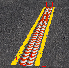
- 2 - Elevated
- The value parameter specifies the height of the divider and the width of the side strips.
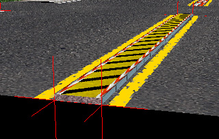
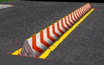
- 3 - Wedged
- A wedged divider is always one metre high. The top of the sloping sides are always 0.5 metres towards the center of the road from the given divider vertices. The remaining width between the two divider vertices are filled by a flat top strip.


Flags
Only two flags are known, besides the two type bits, those control the closing of the short-ends of the divider. Bit seven closes the divider at the start and bit eight closes the divider at the end. The first section of a divided road should close it's start, the last section should close it's end. Intermediary sections shouldn't close anything.
Textures
All dividers in these examples use the same textures as indicated in this image:

The texture index, n, in this case n = 5, points to the texture used for the sides of an elevated divider. n + 1 is used for a flat divider, the sidestrips of an elevated divider and the sloping sides of a wedge divider. Texture n + 2 is used for the center strip of an elevated or wedge divider. Finally, texture n + 3 is used to close the dividers.
struct DividedRoad
{
    bit                   lastAttribute;
    bit[4]                type = 0x08;
    bit[3]                subtype = 0x00;
    bit[8]                padding = 0x00;
    ushort                nSections;
    bit[5]                flags;
    bit[3]                dividerType;
    ubyte                 texture;    // Index in the texture list + 1 for the divider
    ushort                value;      // Usage depends on the divider type
    ushort[nSections * 6] vertexRefs; // Indices in the vertex list
}
struct DividedRoad
{
    bit                 lastAttribute;
    bit[4]              type = 0x08;
    bit[3]              subtype != 0x00;
    bit[8]              padding = 0x00;
    bit[5]              flags;
    bit[3]              dividerType;
    ubyte               texture;    // Index in the texture list + 1 for the divider
    ushort              value;      // Usage depends on the divider type
    ushort[subtype * 6] vertexRefs; // Indices in the vertex list
}
Intersections
Where roads meet, some additional attributes are needed to make up the geometry.
Sidewalk strip

A sidewalk strip defines a piece of a sidewalk. The sidewalk is defined by a set of inner and outer vertex indices, repeating a vertex index can be used to bend a sidewalk around a point as shown in the image. The actual geometry will have an additional point 0.15 units above the inner vertex of each cross section.
Road end piece

A special end piece for roads can be made using sidewalk strip attribute 0xa. Normally this attribute makes a regular sidewalk strip with 4 vertices. However, if the first two vertex references are both set to 0 or 1, this attribute makes up a single triangle begin piece or end piece respectively. Vertex references 3 and 4 define the two bottom vertices for the end piece. Another vertex is generated 0.15 units above vertex 3 (vertex 1 in the picture) to form the triangle.
struct SidewalkStrip
{
    bit                   lastAttribute;
    bit[4]                type = 0x01;
    bit[3]                subtype = 0x00;
    bit[8]                padding = 0x00;
    ushort                nSections;  // Number of cross-sections
    ushort[nSections * 2] vertexRefs; // Indices in the vertex list
}
struct SidewalkStrip
{
    bit                 lastAttribute;
    bit[4]              type = 0x01;
    bit[3]              subtype > 0x01;
    bit[8]              padding = 0x00;
    ushort[subtype * 2] vertexRefs; // Indices in the vertex list
}
Crosswalk rectangles
A rectangular surface representing a cross-walk.
struct CrosswalkRectangle
{
    bit             lastAttribute;
    bit[4]          type = 0x04;
    bit[3]          subtype = 0x04;
    bit[8]          padding = 0x00;
    ushort[subtype] vertexRefs; // Indices in the vertex list
}
Road triangle fans
A road triangle fan is encoded the same way as a regular triangle fan.
struct RoadTriangleFan
{
    bit                    lastAttribute;
    bit[4]                 type = 0x05;
    bit[3]                 subtype = 0x00;
    bit[8]                 padding = 0x00;
    ushort                 nTriangles; // Number of triangles
    ushort[nTriangles + 2] vertexRefs; // Indices in the vertex list
}
struct RoadTriangleFan
{
    bit                 lastAttribute;
    bit[4]              type = 0x05;
    bit[3]              subtype != 0x00;
    bit[8]              padding = 0x00;
    ushort[subtype + 2] vertexRefs; // Indices in the vertex list
}
Buildings
Most of the buildings in a city is constructed using PSDL attributes. These are well suited for low detailed buildings. For higher detail levels, add INST-placed PKGs as parts of or complete buildings.
Roof triangle fans
The roof of a building is made up of triangle fans. These fans differ from the regular triangle fan in that the vertex count is indicated differently. Another difference is that they include a reference to a height value that will replace the y-component of each of the referenced points.
struct RoofTriangleFan
{
    bit                   lastAttribute;
    bit[4]                type = 0x0c;
    bit[3]                subtype = 0x00;
    bit[8]                padding = 0x00;
    ushort                nVertices;  // Number of vertices - 1
    ushort                heightRef;  // Index in the height list
    ushort[nVertices + 1] vertexRefs; // Indices in the vertex list
}
struct RoofTriangleFan
{
    bit                 lastAttribute;
    bit[4]              type = 0x0c;
    bit[3]              subtype > 0x01;
    bit[8]              padding = 0x00;
    ushort              heightRef;  // Index in the height list
    ushort[subtype + 1] vertexRefs; // Indices in the vertex list
}
Facade bounds
To simplify collision detection, each facade has a single quad bound surface. When facades are divided into several sections with different texture maps, it is not necessary to check for collisions against every subdivision since they are all covered by a single quad. Checking against this quad is sufficient. The quad is constructed by taking the two given vertices as the bottom side of the quad and then substituting the y-component in these vertices to construct the corresponding vertices at the top of the quad. This means that the top of a facade bound is always perfectly horizontal, but this is also the case for the facades and the roofs. The bottom edge of the facade bound can, however, be slanted. This acommodates the possibility of a sliver on the facade.
struct FacadeBound
{
    bit    lastAttribute;
    bit[4] type = 0x07;
    bit[3] subtype = 0x04;
    bit[8] padding = 0x00;
    ushort angle; // Angle between 0-255 determines the angle
                  // between the facade and the sunlight
    ushort top;   // Index in the height list
    ushort left;  // Index in the vertex list
    ushort right; // Index in the vertex list
}
Slivers

The ground floor of a building is often partially below street level. To simulate this, there is an attribute that accepts different y-components on the two bottom vertices. This means that the bottom edge of the facade can be slanted so that it follows the street outside the building. The top edge of the sliver is always horizontal, though.
A small remark about slivers is that the texture scale is in fact a reference to the height list. Usually these values are very small (e.g. 0.25) and should not be interpreted as heights for buildings. The algorithm that MM2 uses to calculate the texture coordinates for this attribute is a bit tricky. The texture is uniformly scaled but in the horizontal direction it is shrinked (or stretched) to fit the building. The calculations of the U and V coordinates are shown in the image.
struct Sliver
{
    bit    lastAttribute;
    bit[4] type = 0x03;
    bit[3] subtype = 0x04;
    bit[8] padding = 0x00;
    ushort top;          // Index in the height list
    ushort textureScale; // Index in the height list
    ushort left;  // Index in the vertex list
    ushort right; // Index in the vertex list
}
Facades
A regular facade is modelled as a rectangle that has a texture map repeated a number of times over its surface. The facade rectangle is always aligned with the world Y axis.
struct Facade
{
    bit    lastAttribute;
    bit[4] type = 0x0b;
    bit[3] subtype = 0x06;
    bit[8] padding = 0x00;
    ushort bottom;  // Index in the height list
    ushort top;     // Index in the height list
    ushort uRepeat; // Number of times to repeat the texture along its u-axis
    ushort vRepeat; // Number of times to repeat the texture along its v-axis
    ushort left;    // Index in the vertex list
    ushort right;   // Index in the vertex list
}
Tunnels and railings
The 0x9 attribute family is used for rendering tunnels and railings in MM2; subtype 3 being used for roads only and subtype 0 for all sorts of blocks (mainly intersections).
Tunnels and railings use 6 textures, defined in the preceding texture attribute:
- Left wall
- Right wall
- Ceiling
- Right outside/top thick wall
- Left outside/top thick wall
- Ground, facing down
Subtype 0 (junction tunnel/railing) ignores wall textures 2 and 4, and instead uses 1 and 5 for all walls.
Road tunnel/railing
This type of tunnel attribute applies to roads. The subtype indicates the size of the attribute (number of shorts). The only common version of this attribute is 0x4b (subtype 3), as used in San Francisco and London.
MM2 will render walls along any of the roads following this attribute.
struct RoadTunnel
{
    bit    lastAttribute;
    bit[4] type = 0x09;
    bit[3] subtype = 0x03;
    bit[8] padding = 0x00;

    bit    leftSide         // enables left side
    bit    rightSide        // enables right side
    bit    style            // railing = 0 or wall = 1
    bit    flatCeiling      // ignored if curved ceiling is used
    bit    closedStartLeft  // closes the start of the left wall
    bit    closedEndLeft    // closes the end of the left wall
    bit    closedStartRight // ...
    bit    closedEndRight

    bit    curvedCeiling    // subdivided ceiling
    bit    offsetStartLeft  // chamfers the start of the left wall
    bit    offsetEndLeft    // chamfers the end of the left wall
    bit    offsetStartRight // ...
    bit    offsetEndRight
    bit    curvedSides      // subdivided sides
    bit    culled           // disables outer faces if railings are used
    bit    unknown          // probably unused

    ubyte  unknown1         // padding?
    ubyte  height1          // height of the left and right sides
    ubyte  unknown2         // padding?
    ubyte  height2          // usage unknown
}
In the files of MM2 Beta 1, the PSDL file "banktest.psdl" was found, which uses the attribute 0x4a (subtype 2). As its subtype indicates, this attribute is 2 bytes shorter than the version described above. This might explain why there is a second (unused?) height value.
Junction tunnel/railing
This type of tunnel attribute can be used for any type of block, but is mainly used for intersections. It uses the same parameters for the appearance of the tunnel as the version for roads. The only difference is that this attribute allows more control over the visibility of the walls. This is done in form of a bit array, each bit referencing to a perimeter point of the PSDL block. For example, if the first bit is set to 1, MM2 will render a wall between perimeter point n and 0. If the second bit is set to 1, a wall will be rendered between perimeter point 0 and 1, and so on. Often the array is padded with trailing zeros to match the attribute's size, which is defined in the first ushort.
struct TunnelJunction
{
    bit    lastAttribute;
    bit[4] type = 0x09;
    bit[3] subtype = 0x00;
    bit[8] padding = 0x00;

    ushort nSize;           // number of shorts

    bit    leftSide         // enables left side
    bit    rightSide        // enables right side
    bit    style            // railing = 0 or wall = 1
    bit    flatCeiling      // ignored if curved ceiling is used
    bit    closedStartLeft  // closes the start of the left wall
    bit    closedEndLeft    // closes the end of the left wall
    bit    closedStartRight // ...
    bit    closedEndRight

    bit    curvedCeiling    // subdivided ceiling
    bit    offsetStartLeft  // chamfers the start of the left wall
    bit    offsetEndLeft    // chamfers the end of the left wall
    bit    offsetStartRight // ...
    bit    offsetEndRight
    bit    curvedSides      // subdivided sides
    bit    culled           // disables outer faces if railings are used
    bit    unknown          // probably unused

    ubyte  unknown1         // padding?
    ubyte  height1          // height of the left and right sides
    ubyte  unknown2         // padding?
    ubyte  height2          // usage unknown

    short  unknown3         // controls something about the visibility of the ceiling (more bits?)

    ushort[nSize - 4] enabledWalls // Each bit is used to indicate the visibility of a wall
                                   // (see description above)
}